FAD - Finger Aided Design: Novel Indirect Touch Input Techniques Applied to Finger-Forming 3D Models
Prototype
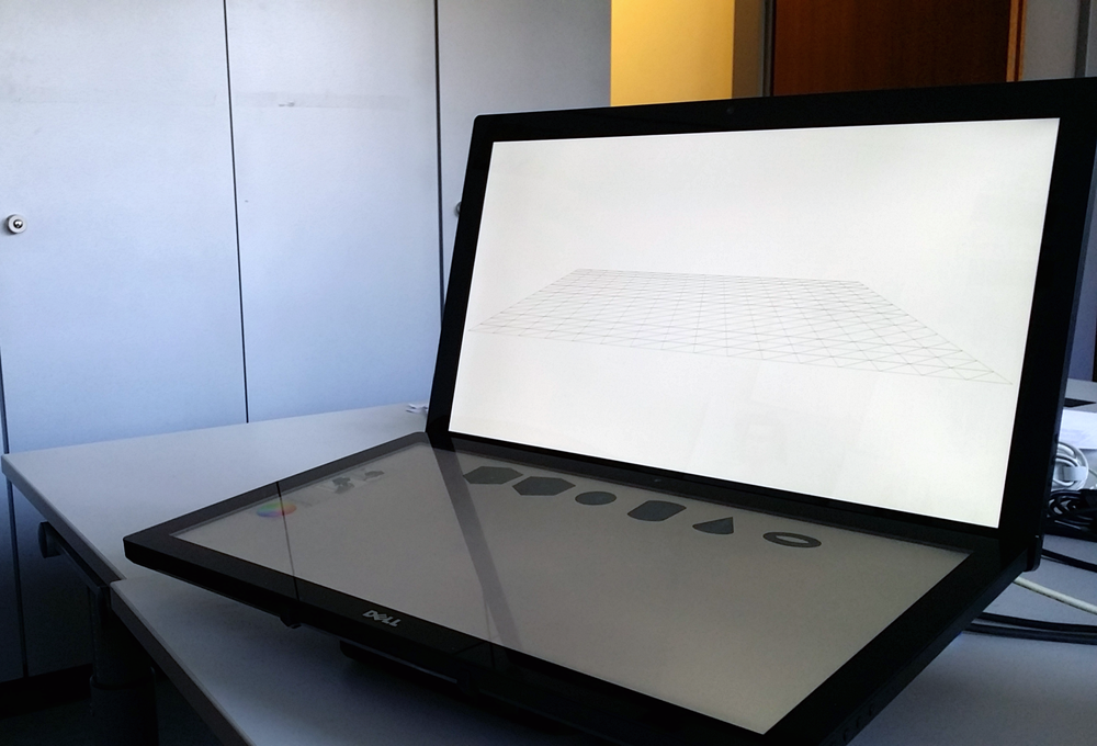
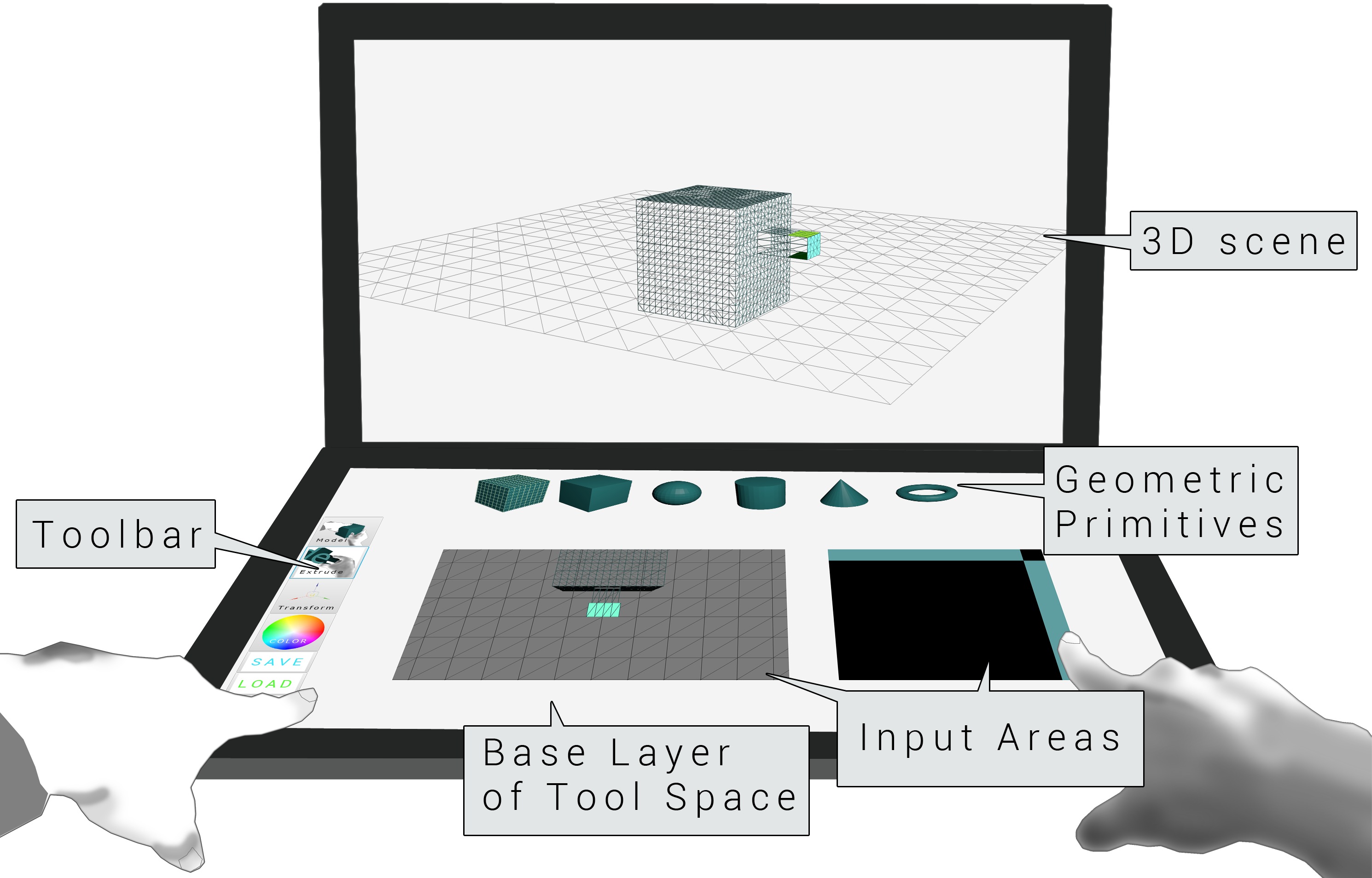
FAD consists of two touch-sensitive surfaces, one horizontally and one vertically positioned. We chose this screen arrangement since we envision our techniques to be integrated into conventional desktop environments enhancing keyboard and mouse input rather than as a separate setup. FAD is developed based on JavaFX 8 and currently runs on a HP desktop PC with a 2.8 GHz Intel Core i7 CPU, an ATI Radeon HD5670 graphics card and two Dell S2340T touch displays with a resolution of 1920 x 1080 pixels each.
Edge-loop scaling
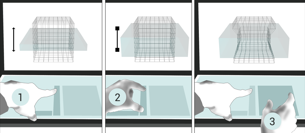
The bimanual edge loop scaling workflow: (1) the non-dominant hand translates and (2) scales the selection volumen, the dominant hand scales the contained edge loops (3).
Extrusion
Implementation
On Touch Start: When a touch gesture is initiated on the extrusion touch pad, the 2D touch coordinated are used to determine, whether the touch occurred on one of the constraining bars or not. Further, a time stamp is set.
On Touch Moved: The actual extrusion logic is handled by an event handler that is executed on every touch movement update. The following pseudocode illustrates the procedure that runs on every touch movement update.
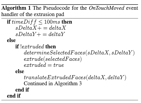
The variable timeDiff is the difference of the current system time and the time stamp set at the onTouchStart event handler. As long as this time difference is smaller or equal to 100 ms, the touch movement deltas are summed up in the variables sDeltaX und sDeltaY. After the first 100 ms of the touch movement, these sums of the two deltas are used in combination with the current camera viewpoint to determine which polygons to extrude. Then, the insertion of the new vertexes is triggered with the extrude()-function.
After the insertion, the current deltas of the touch movement are used to translate the new polygon. The translation causes a mesh deformation and is the visual modeling step during the extrusion. It can be constrained to the surface normal (the polygon's local Z-axis) by starting the dragging movement in one of the constraining bars of the extrusion pad. In this case, a vector that is the result of a multiplication of the surface normal and a factor depending on the touch movement delta is added to each vertex. Currently, the factor is the time-dependent input movement pixel delta divided by 50, which worked well during testing. Whether the horizontal or the vertical touch movement delta is used also depends on the viewing orientation of the selected polygons. If the dragging is not initiated within one of the constraining bars, then the new vertexes are additionally translated by either the polygon's local X- or Y-axis, also depending on the current viewing orientation of the polygon.
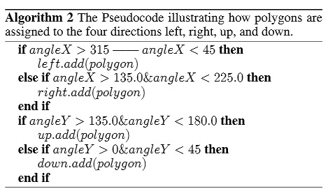
Assigning Polygons to Left, Right, Up or Down
After each extrusion movement (OnTouchFinished) and after each change of the camera viewpoint (on the base layer of tool space), all newly created polygons are assigned to one of the following directions: left, right, up or down. This is done by constructing local coordinate axes of the camera and calculating angles between them and the polygons' surface normals. The camera's local Z-axis is the vector from its current position to the center of the 3D object (as the camera orbits around the object, it always looks at this point), its local X-axis can be calculated as the cross product of an up-vector (0,1,0) and its Z-axis, and its Y-axis can be calculated as the cross product of its Z-axis and its X-Axis. Subsequently, the angles between the camera's X- and Y-Axis and the polygons' surface normals are calculated and used to determine whether the polygons face to the right or left, up or down from the camera's perspective (see algorithm 2 below, whereas angleX is the angle between the camera's X-axis and the polygon's surface normal and angleY the angle between the camera's Y-axis and the polygon's surface normal).
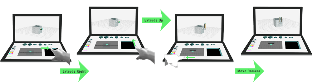
Initial Extrusion
The initial extrusion of polygons selected in the polygon selection tool is a special case in FAD, as there are no other polygons facing in other directions that can be extruded yet. In this case, the touch input of the extrusion pad is used to insert the new geometry into the mesh and to translate the new polygons in the manner described above. 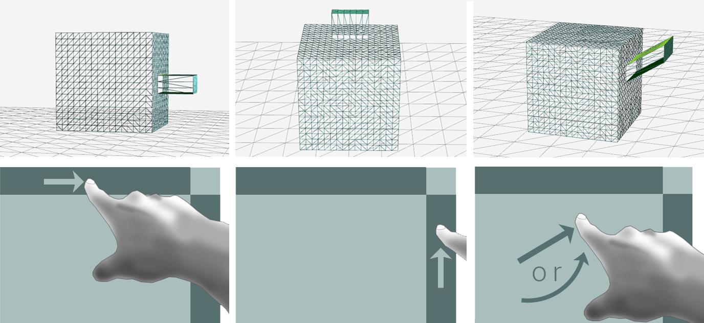
Bent Extrusion with Scene Navigation
The sequential style of alternating extrusion and transformation commands make it a tedious task to create bent shapes step-by-step as many extrusions and rotations are involved. Therefore, this task is often approached with special commands that allow to extrude along a previously drawn curved line, which sometimes requires the user to explicitly specify the number of divisions (extrusions). The higher the amount of divisions, the closer the curved line is approximated by the extruded geometry.
While this approach is integrated in many software packages (e.g. Blender, Maya, SketchUp), the simplification it offers goes along with the necessity of learning a new tool that partitions the modeling process in a sequence of steps and requires abstract knowledge, as the result will only be visible after creating a line and applying the respective extrusion command.
Our idea was to explore a more integral way of extruding bent shapes that does not require a special tool and will display effects immediately. Therefore, we built upon the bimanual control of extrusion and navigation and developed a workflow which allows to create bends and twists by rotating the camera with the non-dominant hand while extruding polygons with the dominant hand.
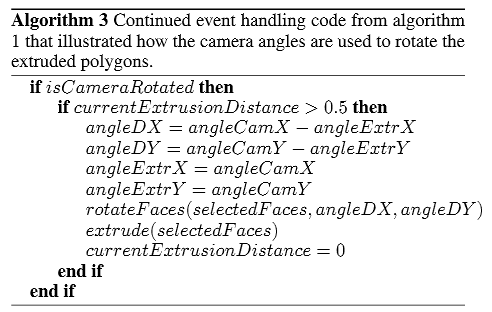
In particular, while the camera is moved during an extrusion touch movement, the polygons currently being translated are rotated and extruded automatically in small regular intervals. This is achieved by (a) measuring the distance between the polygons currently being translated and the polygons that were extruded before and (b) extruding again after a the distance has reached a certain threshold value. The rotation of the automatically extruded faces is dependent on two angle deltas: the camera's rotations around the object's X- and Y-axis since the last extrusion (see algorithm 3). This means, that after a bent extrusion has been finished, the angles the camera was moved around the object's X- and Y-axis correspond to the sum of the angle deltas used to rotate the polygons extruded during the bimanual motion.
Downloads
Download NetBeans projectDependency: Collada Model Loader
