Sketching with Hardware
Day 2
GIF by Robin Davey, http://robindavey.co.uk/
Course Overview
| 1 | Monday | Fundamentals, Keyboard Hacking, Experiments |
|---|---|---|
| 2 | Tuesday | Arduino, Project Topic |
| 3 | Wednesday | Brainstorming Day |
| 4 | Thursday | Own Project |
| 5 | Friday | Own Project |
| Saturday | — | |
| Sunday | — | |
| 6 | Monday | Own Project |
| 7 | Tuesday | Final Presentation, Wrap Up |
Day 2
| 09:00 | Arduino Introduction |
|---|---|
| 10:00 | Analog IO |
| 11:00 | Sketching Circuits |
| 12:00 | Break |
| 13:00 | More Sensors |
| 14:00 | Whatever you like |
| 15:00 | Introduction to our Topic |
| 16:00 | Brainstorming Ideas |
"Hello, Computer!"
II
Quelle: UTEXAS
Arduino
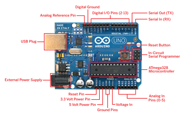
Image Source: ArduinoArts
Arduino — Connected
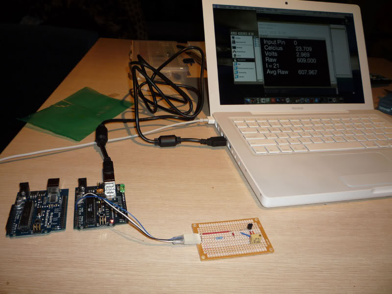
Image Source: SirLeech
Arduino provides (some) power
Arduino provides (some) power
Digital Input/Output
Digital Output
Blinking LED
void setup() {
	pinMode(12, OUTPUT);	// Make pin an output for us
}
void loop() {
	digitalWrite(12, HIGH);	// Set pin to be "+" (on)
	delay(500);
	digitalWrite(12, LOW);	// Set pin to be "-" (off)
	delay(500);
}
Digital Output
High Load!
Digital Output
Transistor / MOSFET
Digital Output
Transistor / MOSFET
Digital Output
Transistor / MOSFET
Digital Input
Pull a pin "up" (+)
void setup() {
	pinMode(2, INPUT);	// Make pin an input for us
}
void loop() {
	value = digitalRead(2);	// Read what's on that pin
}
Digital Input
Pull a pin "down" (-)
void setup() {
	pinMode(2, INPUT);	// Make pin an input for us
	digitalWrite(2, HIGH);	// Activate internal pull-up
}
void loop() {
	value = digitalRead(2);	// Read what's on that pin
}
Digital Input
Using a Bread Board
Analog Input/Output
Arduino Analog Input
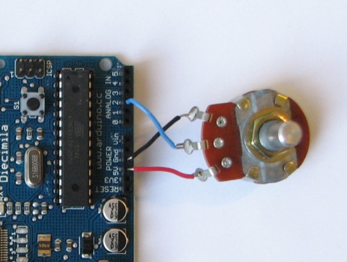
int potPin = 2;	// select the input pin for the potentiometer
int ledPin = 13;	 // select the pin for the LED
int val = 0;	 // variable to store the value coming from the sensor

void setup() {
	pinMode(ledPin, OUTPUT);	// declare the ledPin as an OUTPUT
}

void loop() {
	val = analogRead(potPin);	// read the value from the sensor
	digitalWrite(ledPin, HIGH);	// turn the ledPin on
	delay(val);		// stop the program for some time
	digitalWrite(ledPin, LOW);	 // turn the ledPin off
	delay(val);		// stop the program for some time
}
Analog Output
PWM — Pulse Width Modulation
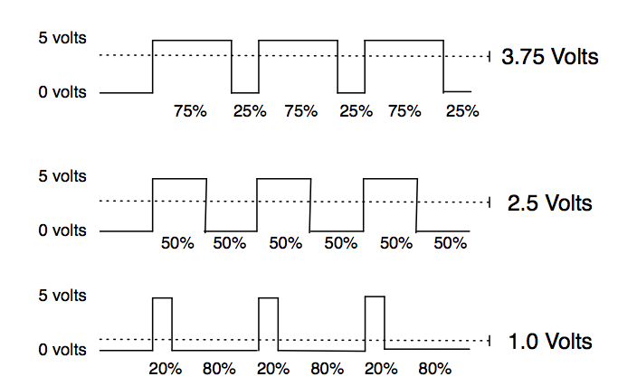
Analog Output
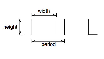
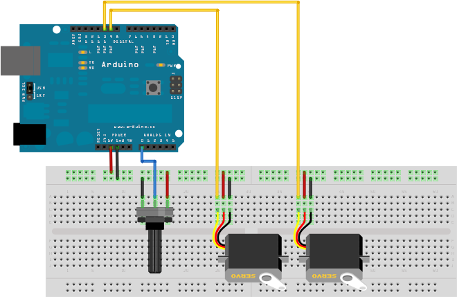
Analog Output: Servo
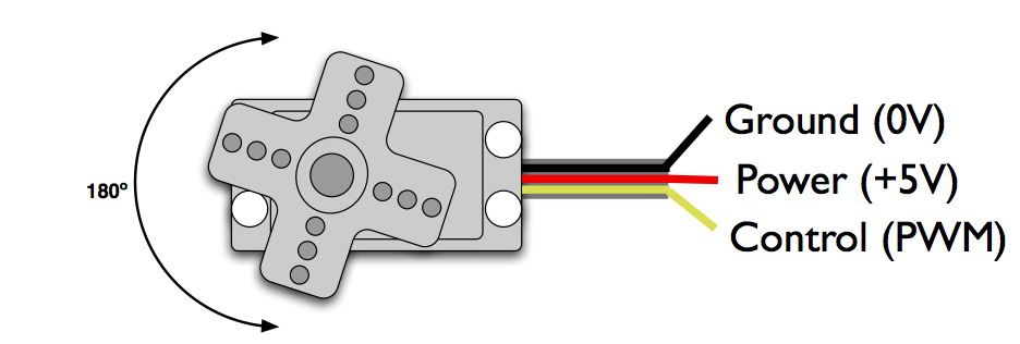
- PWM freq is 50 Hz (i.e. every 20 ms)
- Pulse width ranges from 1 to 2 ms
- 1 ms = full anti-clockwise position
- 2 ms = full clockwise position
Analog Output: Servo
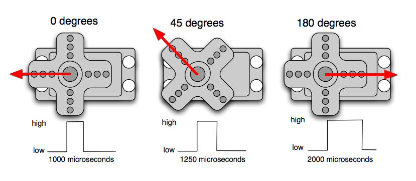
Analog Output: Servo
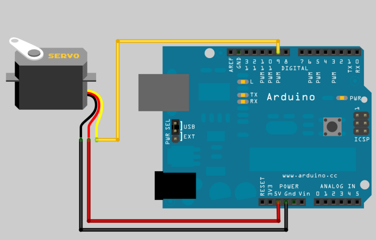
"Servos, Oida!" ☺
Analog Output: RGB LED
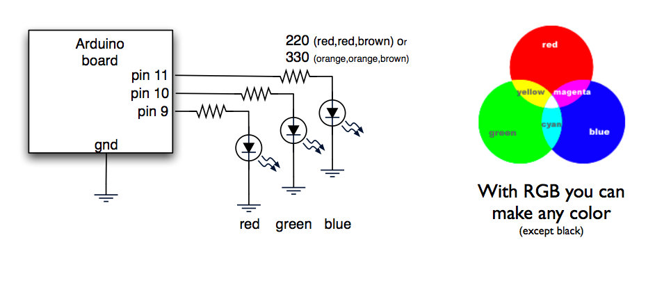
Pins: R G − − B B
GND = Cathode = −
Motor ansteuern
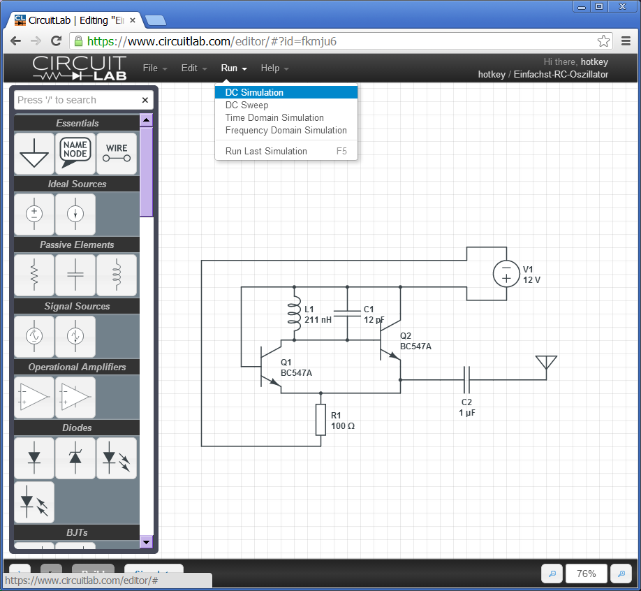
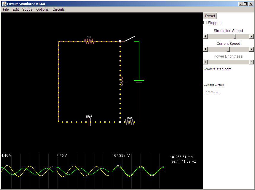
Sketching Circuits
CircuitLab
Circuit Simulator
EAGLE
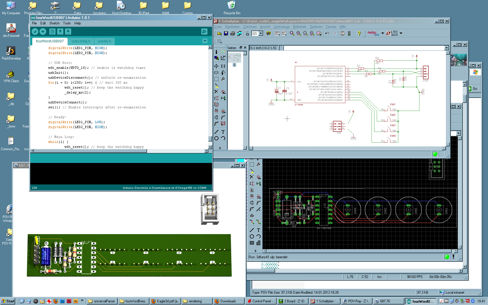
Fritzing
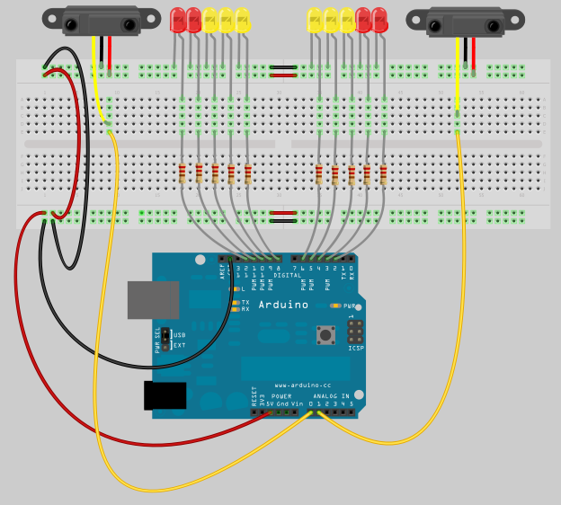
More Sensors
- Light
- Temperature
- Distance (Infra Red, Ultra Sonic)
- Magnetic Sensors (Reed, Hall-Effect)
Actuators
- Motors
- Servos, Steppers
- Speakers
- Solenoids
- LEDs (RGB)
- Piezos
Topic ...
Topic:
IooT
Internet of old Things
Image Source: OX Blog
Features
- Give old things some modern functions!
- Make things communicate!
- Think Steampunk!
Image Source: Business Korea
Hardware
- Microcontroller: Arduino UNO/MEGA
- WiFi: ESP8266
- Bluetooth: HC-05
Recommended Search Terms
- IoT
- Hacking
- DIY
Brainstorming!
GIF by Robin Davey, http://robindavey.co.uk/
Brainstorming!
- Project Name
- Main Idea
- Features
- Sensors? Actuators?
- Software? Complexity? Costs?
- Plan B?
Raus an die frische Luft!
Image Source: Heinrich Kopp: KinderreigenHomework: Elaborate.
- Present your final ideas tomorrow.
- Don't forget to document everything!